How to Use Thermal Shock Chambers to Detect Potential Failures in EV Battery Packs Early
Author:LINPIN Update Time:2025-08-15 Source:LINPINIn the era of electrification, the battery pack is the "heart" of an electric vehicle. Its failure doesn’t just reduce range—it can lead to severe safety incidents and massive recall costs. Imagine identifying hidden defects in cells and structural components that only manifest under sudden temperature swings—before mass production begins. This isn’t science fiction; it’s precise engineering made possible with thermal shock chambers, transforming millions in potential repair and liability costs into manageable design improvements.
This guide systematically explains how thermal shock testing can uncover latent failures in battery packs, helping companies minimize quality risks while maximizing safety and brand reputation.
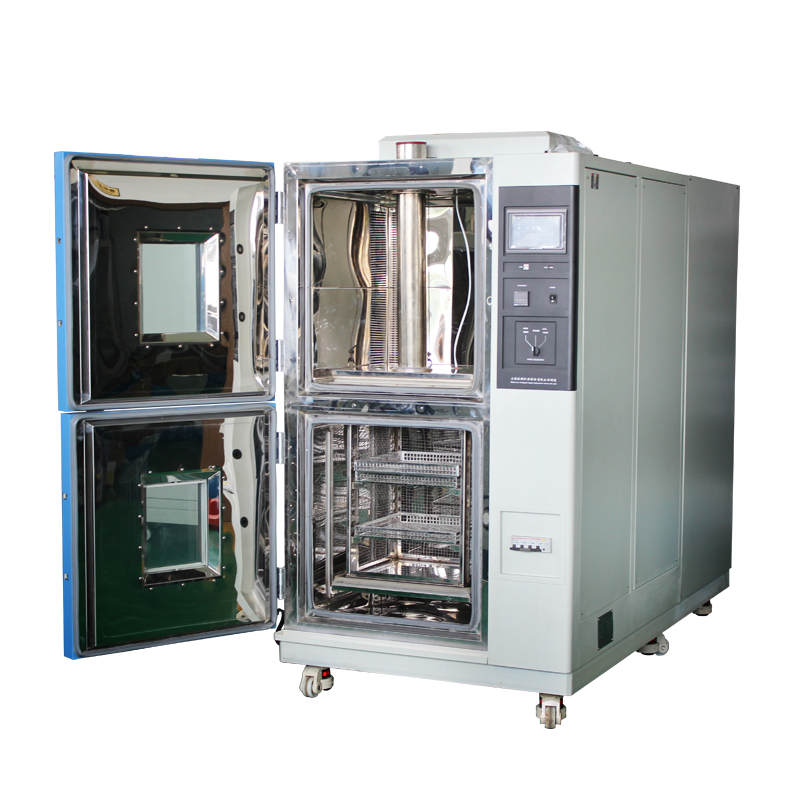
1. What Is a Thermal Shock Chamber, and What Can It Do?
- Definition & Principle: A thermal shock chamber rapidly cycles samples between extreme temperature zones (e.g., -40°C to +85°C) to induce abrupt thermal stress and fatigue.
- Key Capabilities:
- Simulates real-world temperature shocks (e.g., day-night swings, rapid charging heat spikes, cold starts).
- Triggers material/structural responses (expansion, contraction, delamination).
- Controllable Parameters: Temperature range, transition speed, dwell time, cycle count, and optional humidity.

2. Why Do EV Battery Packs Need Thermal Shock Testing?
- Multi-Material Interface Risks: Cells, busbars, adhesives, and seals have mismatched thermal expansion coefficients, risking cracked bonds, solder fatigue, or seal failure.
- Electrical Connection Reliability: Joints (welds, bolts, connectors) degrade under shear stress, leading to resistance spikes, arcing, or intermittent faults.
- Cell-Level Defect Acceleration: Sudden temperature shifts exacerbate electrolyte leakage, gas buildup, or separator tears, exposing latent flaws (e.g., microcracks, dendrites).
- Sealing & IP Rating Validation: Thermal cycling causes gasket hardening or microcracks, compromising waterproofing.
- Thermal Management System Risks: Coolant leaks, heat pipe failures, or TIM (thermal interface material) degradation under repeated shocks.
3. Typical Failure Modes Revealed by Thermal Shock Testing
- Cracked solder joints/welds → resistance fluctuations
- Adhesive delamination or aging
- Microcrack propagation in electrodes/separators → internal shorts
- Structural deformation (housing, load-bearing parts)
- Seal failures → coolant/water ingress
- BMS (Battery Management System) sensor drift or connector failures
4. Step-by-Step: Designing an Effective Thermal Shock Test Plan
Step 1: Define Objectives & Risk Areas
- Use DFMEA (Design Failure Mode Effects Analysis) to prioritize weak points: welds, seals, high-stress zones.
Step 2: Set Test Conditions
- Temperature Range: Align with operational extremes (e.g., -40°C to +85°C for automotive; -55°C to +125°C for aerospace).
- Transition Speed: Mimic real-world shocks (e.g., <5 min between extremes).
- Cycle Count: 500–1,000+ cycles (accelerated aging).
- Dwell Time: Ensure thermal equilibrium (e.g., 30–60 min per extreme).
Step 3: Prepare Samples & Instrumentation
- Test full packs or critical subassemblies (modules, cooling systems).
- Instrument with:
- Thermocouples/IR cameras for hotspot detection.
- Strain gauges for mechanical stress.
- Continuous electrical monitoring (voltage, resistance, insulation).
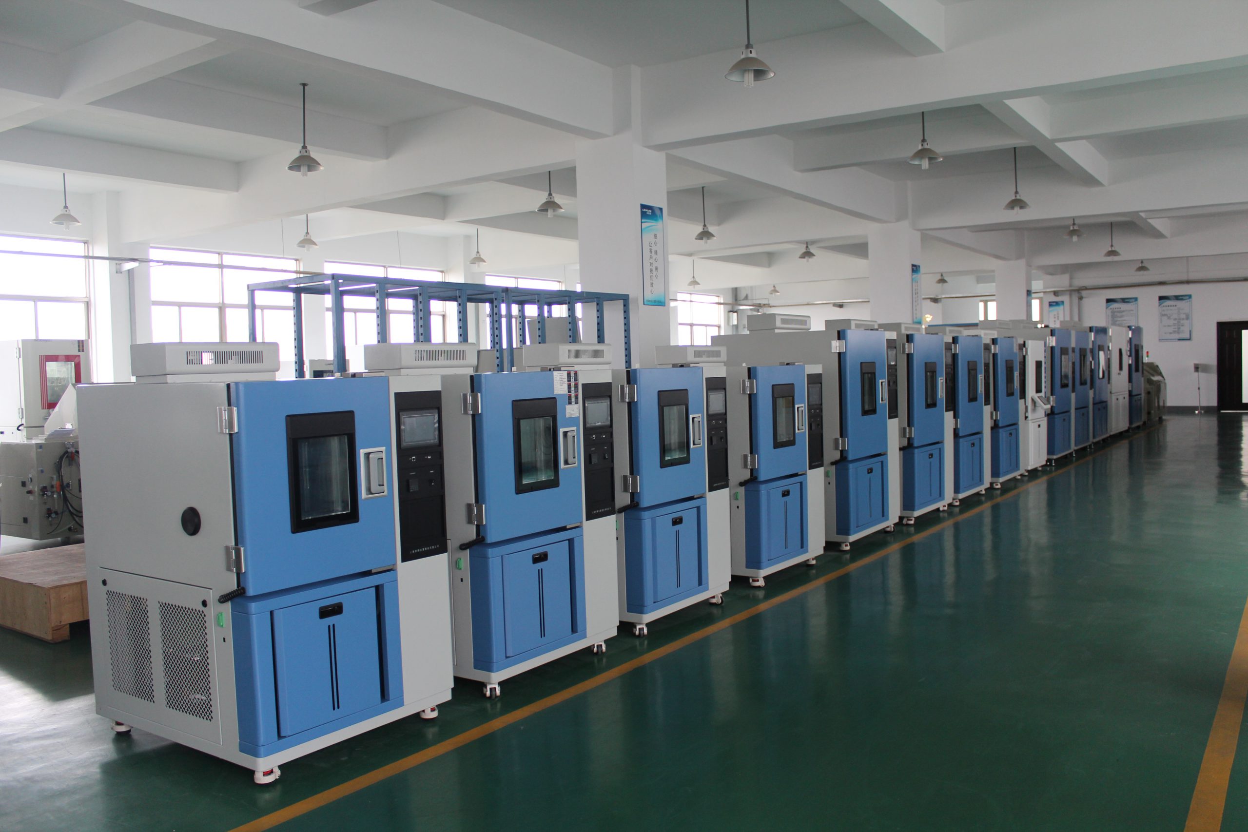
Step 4: Execute & Monitor
- Perform intermittent checks (every 100–300 cycles):
- Electrical tests (capacity, insulation resistance).
- Visual/NDT inspections (X-ray, ultrasound) for internal defects.
Step 5: Failure Analysis & Redesign
- Root Cause Analysis (RCA): Cross-section failed welds, SEM/EDS for material degradation.
- Design Fixes: Optimize materials (e.g., flexible adhesives), reinforce weak joints, improve cooling.
5. Advanced Detection Methods for Enhanced Insights
- Electrical: Monitor cell voltage imbalance, contact resistance.
- Thermal/Mechanical: IR imaging, strain gauges.
- NDT: X-ray/CT scans for hidden cracks.
- Gas Analysis: Detect electrolyte off-gassing.
- High-Speed Video: Capture seal breaches or swelling.
6. Engineering Applications & ROI
- Early R&D: Catch design flaws before tooling.
- Pre-Production Validation: Reduce batch failures.
- Supplier QC: Set standards for critical components (e.g., cooling plates).
- Reliability Growth: Accelerate failure replication for faster fixes.

7. Best Practices & Pitfalls to Avoid
- Avoid Over-Testing: Extreme parameters (e.g., -70°C) may yield unrealistic failures.
- Statistical Rigor: Test multiple samples/batches for confidence.
- Safety Protocols: Remote monitoring for thermal runaway risks.
- Combined Stresses: Pair with vibration/humidity tests for real-world simulation.
Don’t let thermal shocks become your product’s Achilles’ heel. A thermal shock chamber transforms hidden risks—electrical degradation, seal failures, material fatigue—into actionable data, providing quantifiable proof of reliability and a roadmap for improvement.

