How Humidity Control in Thermal-Humidity Chambers Impacts Your Test Results
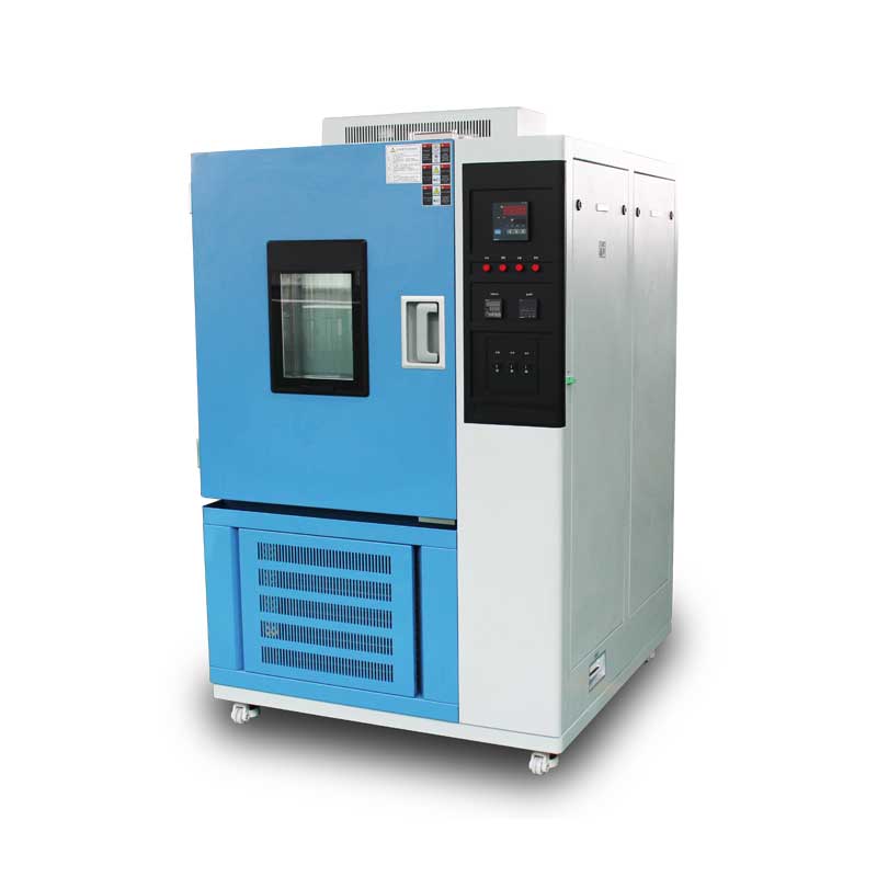
Author:LINPIN Update Time:2025-08-27 Source:LINPINIn environmental-reliability testing, thermal-humidity chambers are the workhorses that replicate extreme temperature and moisture conditions. Whether you are qualifying an automotive ECU, a satellite PCB, or a consumer handset, field performance and service life are ultimately decided in these cabinets. Too often, however, engineers fixate on temperature profiles while treating humidity as a “background” parameter. That oversight can invalidate data, shorten projected life, and even cause a certification audit to fail.
Why is humidity control so critical, and how exactly does it steer test outcomes? Below we break down the physics, map out industry-specific risks, and give practical steps to tighten humidity accuracy.
1 The Science—and Stakes—of Humidity Control A modern chamber balances heating, cooling, humidifying, and de-humidifying subsystems to deliver tightly coupled temperature/RH profiles. Three design choices decide how well that balance is maintained:
• Humidification method
– Steam injection: highest precision, slower ramp, higher energy
– Ultrasonic: fastest response, risk of droplet carry-over
– Spray atomization: economical, can create cold spots
– Steam injection: highest precision, slower ramp, higher energy
– Ultrasonic: fastest response, risk of droplet carry-over
– Spray atomization: economical, can create cold spots
• De-humidification method
– Mechanical refrigeration: most common, reliable down to ~10 %RH
– Desiccant wheel: for ultra-dry (<5 %RH) or rapid pulldown
– Dry-air purge: simple, but wastes conditioned air
– Mechanical refrigeration: most common, reliable down to ~10 %RH
– Desiccant wheel: for ultra-dry (<5 %RH) or rapid pulldown
– Dry-air purge: simple, but wastes conditioned air
• Sensor technology
– Capacitive thin-film: ±1 %RH typical, prone to drift above 85 °C
– Chilled-mirror: ±0.5 %RH, immune to most contaminants, higher cost
– Capacitive thin-film: ±1 %RH typical, prone to drift above 85 °C
– Chilled-mirror: ±0.5 %RH, immune to most contaminants, higher cost
When humidity drifts, three failure modes follow:
-
Data corruption—material swell, insulation resistance drop, optical fogging.
-
Field failures—corrosion of solder joints, dendritic growth, MEMS stiction.
-
Certification red flags—MIL-STD-810, IEC 60068, and automotive specs all have hard RH tolerances.
2 Industry-Specific Impact
Electronics
• High RH (>85 %): leakage paths, electrochemical migration, battery-terminal oxidation.
• Low RH (<10 %): ESD susceptibility, brittleness of epoxy packages.
Case study: A tier-1 handset OEM traced a 15 % yield loss to ±5 %RH swings in a 60 °C/90 %RH soak. Tightening control to ±1 %RH lifted yield by the same 15 %.
Automotive
• Sensor drift: condensate on pressure-sensor membranes caused false barometric readings.
• Elastomer aging: door-seal profiles cracked after repeated 40 °C/95 %RH cycles because humidity spikes accelerated stress relaxation.
• Sensor drift: condensate on pressure-sensor membranes caused false barometric readings.
• Elastomer aging: door-seal profiles cracked after repeated 40 °C/95 %RH cycles because humidity spikes accelerated stress relaxation.
Aerospace
• Altitude-to-tropic transitions: a 1 %RH error at −55 °C shifted composite fatigue life estimates by 8 %.
• Icing tests: super-cooled droplet size is RH-dependent; poor control falsified accretion rates.
• Altitude-to-tropic transitions: a 1 %RH error at −55 °C shifted composite fatigue life estimates by 8 %.
• Icing tests: super-cooled droplet size is RH-dependent; poor control falsified accretion rates.
3 Tightening Humidity Accuracy: Practical Steps
Choose the right method for your band
• If you mainly run steady-state 85 °C/85 %RH, go with steam injection plus mechanical de-humidification.
• For 10 %RH low-dwell tests, spec a desiccant wheel and closed-loop dry-air purge.
• If you mainly run steady-state 85 °C/85 %RH, go with steam injection plus mechanical de-humidification.
• For 10 %RH low-dwell tests, spec a desiccant wheel and closed-loop dry-air purge.
Calibration & hygiene
• Calibrate RH sensors every 6 months or 500 h, whichever comes first.
• Disinfect water tanks monthly; biofilm can clog steam injectors and shift calibration.
• Calibrate RH sensors every 6 months or 500 h, whichever comes first.
• Disinfect water tanks monthly; biofilm can clog steam injectors and shift calibration.
Smart control loops
• Modern systems pair PID algorithms with machine-learning feed-forward: the controller “learns” door-open events, load changes, and even seasonal tap-water temperature. Users report ±0.5 %RH stability versus ±2 %RH for legacy on/off loops.
• Modern systems pair PID algorithms with machine-learning feed-forward: the controller “learns” door-open events, load changes, and even seasonal tap-water temperature. Users report ±0.5 %RH stability versus ±2 %RH for legacy on/off loops.
Humidity is the silent referee that can overturn every other measurement. A 2 %RH excursion that goes unnoticed during a 1000-hour test can erase months of design validation. Specifying a chamber with tight humidity control—and maintaining it—is not just good practice; it is the final line of defense between your product and an expensive field recall.

